GIGA Electronics Ltd


The board contains eight individual circuit sections as identified in the table below. These circuits are typical in most distributed systems providing an excellent test bed for demonstrating non-invasive, in-system measurement, optimization and troubleshooting techniques. Table 1 Circuit Sections on the VRTS3 Board
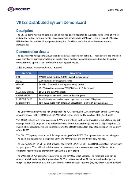
The circuit is a discrete BJT voltage regulator with a 7‐10V input and a 3.3V output. The BJT is controlled by a TL431 shunt regulator. C1 and R5 provide frequency compensation, R2 is the injection transformer terminating resistor and R3 and R4 are the output voltage sense divider. Two different output capacitors can be selected using S1‐1 and S1‐2. One capacitor, an aluminum electrolytic capacitor provides excellent phase margin while the other results in approximately 40 degrees phase margin. A blue LED is powered by the output, providing a visual indication of power on and also a load of approximately 20mA. An additional 25mA of load current can be switched on or off using S1‐3.
Accurate component models are essential to getting useful simulation results. Vendors often leave out the measurement details and so the results might not be what you expect.
These calibrated boards can be used to measure your own components, such as resistors, inductors and capacitors in order to obtain high quality, accurate data for your simulations. The component mounts include high quality standard SMA connectors and support 1 port and 2 port impedance measurements.
The boards come unpopulated, ready for your components to be mounted. The kit includes a variety of test board sizes as noted below, supporting commonly used component package sizes. De-embed files are included are available in three formats, s1p, s2p and CTI. The boards can also be de-embedded using full fixture compensation or impedance calibration available in many popular VNA’s.
Provisions are included for a Bode plot measurement, with the injection resistor, R5, included as well as test-points for the injection signal and measurement (TP3 and TP4). SMA output connectors are also included to simplify connections for many measurements including the 2-port output impedance measurement, step load and other common measurements.
The board is USB powered by connecting a USB cable with a type B connector to the power connector USB1. (CAUTION: R9 and R10 GET HOT - DO NOT TOUCH)
The circuit is an integrated point of load synchronous buck regulator with a 5V input and a 1.2V/2.5A output. The device uses emulated current mode control, making it simple to create a flat impedance output. Easily accessible 0805 chip size components make it easy to customize or experiment with different component values. This is a fully self-contained demo board using USB input power and an on-board resistive load.